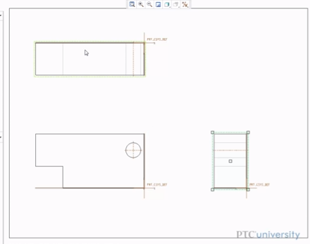
Today, we’re going to look at how to create a drawing file in Creo Parametric. We’ll also look at some basic tools and features that you can use to get started with drawings in Creo Parametric 2.0.

Today, we’re going to look at how to create a drawing file in Creo Parametric. We’ll also look at some basic tools and features that you can use to get started with drawings in Creo Parametric 2.0.
The process of designing new products is more complex than ever before. With multiple partners and manufacturers often involved in any project, clear communication and collaboration are vital. Yet, this comes with its own complexity, especially when manufacturers and supply chain partners are using different CAD tools. It’s not surprising that problems occur; more complex processes, additional costs and increased room for error.
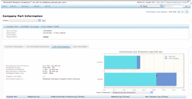
Are you satisfied with the level of feedback provided during product development, including feedback from your supply chain? What if you were able to provide enterprise-level visibility into the risk of missing product performance targets, potential product and material compliance failures, and supply chain disruptions?
Timing is everything. As a designer, engineer or executive in today’s world, you are driven by the demand to get your products to market quickly.
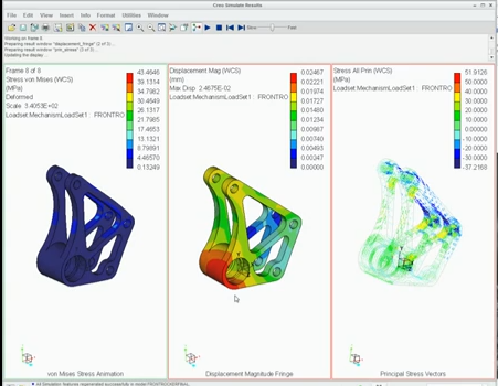
Companies that are designing sophisticated products, with either electro-mechanical or highly engineered components need to balance product development costs, quality and time to market pressures.
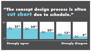
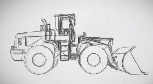
Concept design is crucial to product development. It doesn’t matter whether you use traditional techniques, 2D tools, or 3D tools, getting your concept design right is vital for the subsequent stages of product development. This is where creative and innovative ideas can have the most impact; before a product have been involved in weeks of design development.
In today’s design environment, the ability to leverage a design up and down the design process is critical. But, for many companies, there is a real challenge here; they need to overcome the difficulties of managing interoperability between different environments and tools.
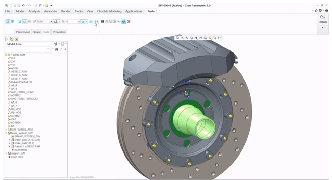
Having to work with non-native CAD files can be a frustrating process. The problem is clear; you have CAD data that you need to work with, but it was created in a different CAD tool to the one that you use. Having a tool that enables you to work with non-native CAD data, without having to recreate it can be invaluable, saving you time and money
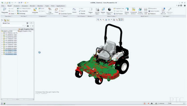
With a large assembly, there are a lot of interconnected parts, which makes it very complex to work with. Often, the model is so complex and it has so many parts that it’s hard for your CAD system to load it all up easily or quickly. This wastes time and means you can’t get on with your work. Also, with large assemblies, it is harder to ensure that all of the different parts work together. With more parts, there are more chances for things to go wrong.

Formula Student 2013 is here. Running from 3rd-7th July 2012 at the world-famous Silverstone circuit, the event showcases the talent and ability of young engineers from around the world.