Having to work with non-native CAD files can be a frustrating process. The problem is clear; you have CAD data that you need to work with, but it was created in a different CAD tool to the one that you use. Having a tool that enables you to work with non-native CAD data, without having to recreate it can be invaluable, saving you time and money
With Creo you are able to open design data from a range of Cad programmes. This is a powerful benefits; it means that engineers and designers are able to work on multi-CAD projects with all of the latest design information. This means you can avoid errors, which are both costly and time consuming.
How does multi-CAD data integrate with Creo?
Non-native files, from systems such as Solidworks and Catia, can be easily assembled and referenced to other geometry. It can also be put into the context of the entire assembly. You can then begin to establish the intelligence in the imported geometry. This includes pattern recognition. By simply selecting a piece of the pattern, Creo can find and establish this design intent. And, once this pattern has been recognised, you can use it to assemble imported or native components multiple times. This process can then be completed quickly and easily for parts such as bolts and screws.
In-built features in Creo help you to work with native and non-native files
To ensure that the design remains up-to-date, you can use the unique Associative Topology Bus technology (shortened to ATB) to maintain the association with the original non-native file. This will allow you to quickly see and incorporate any changes. Now, with your native and non-native parts assembled, you can quickly create new geometry within the context of this multi-CAD assembly, by easily referencing various design details and features. Using an existing 2D profile, you can further define this geometry.
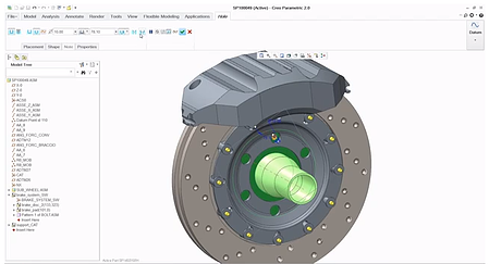
Once the basic geometry creation is complete, you can add detailed features. As shown in the below example, you could create a countersunk hole, aligned to the axis of the feature of a non-native part. You can then use pattern recognition on this non-native part feature to establish design intent in your new geometry. This will allow you to apply this pattern and to quickly and easily propagate the countersunk hole.
Now that you have created the design intent, including the pattern, assembling additional non-native components to your assembly is easy. Due to the associations established between the native and non-native components, when an update is received to a non-native part, the ATB technology propagates the change and reapplies design intent. By working with the context of a multi-CAD assembly, you are able to visualise all components, establish relationships between them, and easily integrate updates to non-native parts. All of this means you can collaborate more effectively with suppliers and partners who are using different CAD systems, helping you to eliminate errors, avoid timely re-works, and shorten the overall design cycle.
To find out more about the power of Creo and how it can help you work with multi-CAD files, try it for free for 30 days: