At their base level, lattices are repeating structures. Spoked wheels and trusses are examples of lattice-based objects that have a basic topology that repeats either consistently or with a degree of variation.
Dealing with lattices in computer aided design has always been tricky, but the pace of technological advancement has given designers increasingly powerful tools that enable latices to be built and manipulated with astonishing ease. Put simply, they’re now a joy to work with.
Nowhere is this more evident than in the latest Creo 4.0 release.
Often referred to as lightweight structures, lattices come in a number of forms. For example, you can use the following types of lattices in Creo 4:
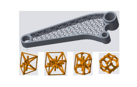
- 2 1/2 D lattices. Extrusion-based and offering multiple cell types, this type of lattice is available in both triangular and honeycomb formations.
- 3D lattices. These are beam-based with multiple 3D cells that include hexagonal and octagonal designs. Each geometry can have different uses and the ability to remove dangling beams is also included.
Regardless of which lattice type you choose to work with in Creo 4.0, the concept of using either 2 1/2 D or 3D lattices remains the same. The user simply selects a lattice unit in order to build a uniform structure that is the result of the cell being multiplied by X, Y and Z. Creo 4.0 can then trim the cells against the volume.
It’s even possible to have multiple lattices within a single part, simply by selecting the volumes contained in the part and adding the relevant lattices.
The implementation of lattice design in Creo 4.0 is exactly as you would expect; it relies on an approachable user interface and tools that enable designers to closely examine and modify every element of their lattices.
To produce a lattice in Creo 4.0, you simply select the volume you wish to convert, select the desired parameters for the lattice and leave the software to do the hard work. Users can even choose from an impressive array of in-fill and pattern options.
Parametrically-controlled lattices can also be optimised thanks to a simulation tool and the Behavioural Modelling extension. Significant effort on behalf of the Creo 4.0 development team has ensured that the data used during such tasks is handled efficiently and parametrically-driven to ensure quick responses to design changes.
3D printing also benefits from the Creo 4.0 update, with a set of additive manufacturing tools included that undertake the pre-processing of geometry. Printability across single parts also benefits from multiple checks and simple STL previewing is bolstered by the ability to build chambers and platforms with automatic nesting tools and previews of support requirements.
Why lattices are beneficial for designers
Creo 4.0 takes lattice design to a whole new level, but why are these structures beneficial for designers?
Lattices offer a few key benefits. In complex designs, they simplify the constituent elements and inherent design issues to a relatively small set of options. Lattices also make the design process for manufacturing more straightforward by providing engineers with a model that encourages them to focus on cell topology, rather than the part design as a whole.
Perhaps most importantly, lattices provide a convenient way to vary a part’s material properties. Those properties can be varied continuously by picking a single cellular topology and varying the thickness of the beams. This frees engineers from traditional, time-consuming methods of design and enables the structural performance of a part to be tuned within a single material and manufacturing process.