Creo Parametric has improved the workflow used to improve sketching. Now, you are able to start sketching after only two clicks. For example, to being to sketch an extrude feature just start the extrude tool (located in the ribbon user interface) and then select the sketch plane. That’s it. Two clicks and you are ready to start sketching. You can also do the reverse. This time, we will select the sketch plane and then the extrude tool. Start by selecting the front datum plane as the sketch plane and then start the extrude tool. Regardless of your approach, after just two clicks you are ready to begin sketching.
Starting to sketch your first part
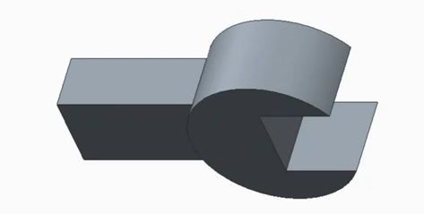
Notice that the sketcher tab is open. This contains all of the tools that you will require for sketching. Then, in addition to this, Creo Parametric starts the sketch in the 3D orientation. In this example, we are going to create a part that looks like the image below:
So, to start, select the circle and use some lines to sketch a slot on the right side. See the image below for an idea of what it should look like:
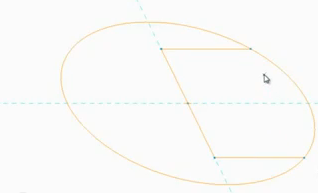
After two pieces of the circle are trimmed away to create a closed loop, you’ll notice that Creo parametric automatically shades closed-loops.
Controlling the dimensions of your sketch is simple. For example, by altering the dimensions of a gap, Creo Parametric will automatically update the sketch to match these new dimensions. The same also applies to arcs, which can be modified using the diameter converter.
Once the sketch is complete, you should then close the sketch tab by right clicking and then selecting ‘Ok’ in the pop-up menu. The other way to close the sketch tab is by clicking ‘Ok’ in the dashboard.
How to sketch in a 2D orientation
Sometimes, it is convenient to sketch in a 2D orientation. To do this, select sketch view in the graphics tool bar. Remember, when you enter sketcher, Creo Parametric doesn’t ask you how you want your sketch orientated. It just guesses. Most of the time, this is perfectly adequate. But, sometimes you might want to change the orientation. To do this, you need to right click and then select section orientation on the pop-up menu and then select vertical reference. After this, you need to select and edge to be vertical:
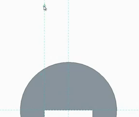
But, in the example below, we want our open end of the feature to be facing down. so, to do this, we need to right click, select section orientation and then select flip section orientation. Now that the sketch is orientated the right way, we can continue sketching.
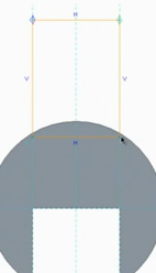
To complete the shape that we are after, we need to add a rectangle that references both vertical edges of the slot. Notice thought that only one of them has a reference already created on it:
The good news is that in Creo Parametric, you don’t have to cancel the rectangle and open the references dialogue box. All you need to do it use the ‘Alt’ key; this allows you to create and use references as you are going along. It means you can continue to sketch uninterrupted. Notice now that a reference line was created and the rectangle now snaps to it:
We also need the bottom of the rectangle to snap to the edge of the arc. To do this, we need to create a reference there too. This is done in the same way as in the example above. Now the rectangle can snap to the intersection of the arc and vertical references.
The new sketcher workflow makes sketching and reference selection much more intuitive. It can be a powerful time saver in your design process.
If you want to know more about the capabilities of Creo Parametric, download the 12 reasons you should upgrade to Creo Parametric 2.0