 With Creo Parametric, designers are able to build assemblies using mechanical connections. This enables them to investigate the motion behaviour of their designs in real-life conditions.
Using mechanisms design, designers are able to detect collisions between moving parts and quickly understand the kinematic implications of design changes.
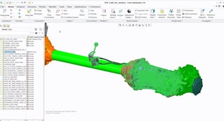
For example, if you wanted to explore a gear box design, you could use this technology to enable clear analysis. Starting with an assembly created using mechanical connections, you can then capture snapshots of the gear box in different positions. Since the assembly is a fully detailed mechanism, not a static assembly, you can change the position by simply dragging the gear stick. As a result, you are able to run a dynamic interference check on the assembly.
As the mechanism moves through it’s complete range of motions, Creo Parametric will detect any interferences and collisions between parts. At the same time, you are also able to establish a motion envelope to avoid collisions, should you add new parts to the assembly.
Analysing the kinematic performance of the design
You are also able to analyse the kinematic performance of the design. To start, apply a set velocity profile to the input shaft, which enables you to set the testing parameters for the gear box design. The velocity profile that you have established is also easy to comprehend, with a clear graph. On top of this, all of the analysis parameters are available to view in the mechanism tree. Now that the input conditions have been set, you can use your captured snapshots to reset the assembly to the desired starting point. Creo Parametric can now quickly analyse the mechanism performance for each gear in real time. Once the analysis is complete, you can then view the results graphically to understand the performance of the mechanism. These results can then be used to optimise your design and also to help confirm that the design meets all of the design requirements.
Integration with PTC Mathcad
Another benefit of using this technology is that it means you can drive your design with PTC Mathcad. As a result, you are able to make changes to highly complex assemblies both quickly and easily. You also can have confidence that the design is fully documented and reusable by other people in your team.
You can even open up the Mathcad table directly in Creo Parametric, enabling you to easily switch parameters. The mechanical assembly then automatically updates to reflect the new design. With the new mechanical assembly in place, you can then re-run the previous analysis, to make sure that the changes you’ve implemented do not cause any new collisions. To do this, simply make a copy of the analysis from the mechanism tree and re-run the analysis to ensure consistency. You can even compare the results from the original analysis and the new analysis that you’ve run, to see whether the design changes that have been made have also resulted in improved performance.
To find out more about using Creo Parametric, try it now for free for 30 days.